Introduction
Recently I looked at how we could use FPGA and softcore MicroBlaze V processors to offload intelligent motor control.
Controlling intelligent motors is however, only one small part of Robotic solutions. The motors enable us to move around in the environment, however sensors such as LIDAR and cameras enable us to navigate safely around in that environment.
In this project we are going to examine how we are able to control and interface with a commonly used LIDAR sensor using a similar approach.
This will enable us to develop a solution which is able to use FPGAs for intelligent motor control, and safely navigating within its environment. The use of two softcore processors one for motor control and the other for environmental sensing enables us to then leverage the programmable logic for more complex algorithms, functional safety features which require determinism and responsivity. The use of a FPGA also enables tight integration of the overall system enabling a more compact and power efficient solution.
LDS-01
The sensor we are using for this project is the LDS-01 from Robotis, this is a a 2D laser scanner which rotates at 300 RPM. It is capable of measuring distances between 120 and 3500 mm with an accuracy of +/- 5%.
This sensor operates from a 5V supply and requires a PWM signal to drive the motor at the required scan rate.
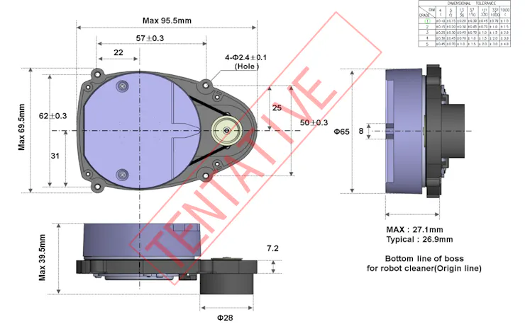
Data is communicated from the LDS-01 using UART operating at 230400 baud.
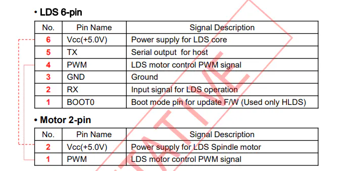
To interface this with the FPGA we need a UART at the correct baud and the ability to generate a PWM.
Hardware Design
We can implement this in any AMD FPGA or SoC, for this experiment I have been using the Arty S7.
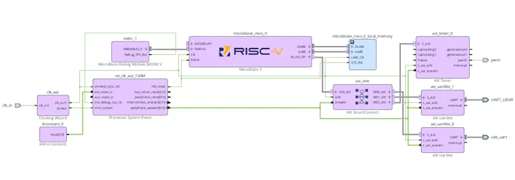
This design is going to have the following
- MicroBlaze V configured as an microcontroller, with 64KB of memory.
- AXI UART Lite connected to the USB UART 230400 baud.
- AXI UART Lite connected to the LDS-01 230400 baud.
- AXI Timer to generate the PWM
- Clock Wizard - generate the clock at 200 MHz.
The final system looks as below
The implementation resources are limited.
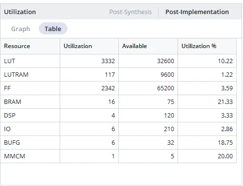
The next step is to export the XSA and start the development of the embedded software development.
Software Architecture
This application needs two kinds of software first the embedded software used to run on the MicroBlaze V.
We also need some software running on the host to plot the data, from the sensor
First lets look at the strucutre of data received from the LDS-01 over the UART link. Instead of sending a full 360° scan at once, the LDS-01 transmits the scan in small blocks:
- 1 packet = 42 bytes
- 1 packet covers 6 degrees of rotation (6 samples, one per degree)
- 60 packets make a full 360° sweep (60 × 6° = 360°)
Each 42-byte packet contains
- Header / sync byte (used to find the start of a packet)
- Angle index (tells you which 6° block this packet belongs to)
- Motor speed (RPM) (2 bytes)
- Six measurement blocks (one per degree within that 6° block)
- Checksum
Each of the six measurement blocks contains :
- Intensity (2 bytes)
- Distance (2 bytes, in millimetres)
- Reserved/flags (2 bytes)
The angle index identifies which 6° segment you’re receiving. You place the six samples into the correct positions in your 360-element scan array using:
base_angle = angle_index × 6- sample angles are
base_angle + 0throughbase_angle + 5
After you’ve received all 60 packets, you have a complete 360° scan.
The packet includes a 2-byte RPM value. This can be used for monitoring rotation speed and compensating for timing skew.
The LDS-01 includes a simple checksum at the end of the packet.
- Sum the first 40 bytes of the packet
- Reduce to 8 bits (mod 256)
- Compute
checksum = 0xFF - sum - Compare against the checksum bytes in the packetIf the checksum doesn’t match, discard the packet and resynchronise on the next header byte.
We can stop or start the stream using simple commands
- Send
bto begin operation - Send
eto pause operation
The LDS-01 connector includes a PWM motor control pin, this needs to be driven by a 50Khz 50% PWM signal.
The embedded software developed in Vitis, is split into two files the first file which contains the main(). performs the configuration and set up along with running the necessary functions for the application.

Hi this is my first post to this blog and i really like this platform made by the great Asig Mughal the king
Thank you so much for the kind words. Regards Asif